
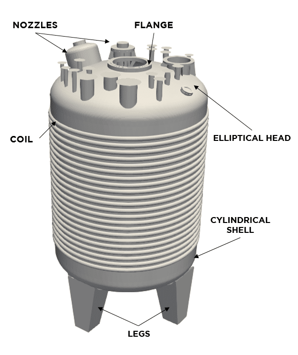
Pressure Vessels are used in the industry to store process fluids under certain temperature and pressure conditions. Commonly, pressure vessels have cylindrical or spherical shape, can be disposed in a horizontal or vertical way and are provided of heads with different shapes (Ellipsoidal, Hemispherical, Toroidal, etc.). These equipments are fitted with different elements such as nozzles (used to control the entry and/or exit of the fluids), cooling or heating jackets to maintain the temperature of the stored fluid, or other non-pressurized elements capable of supporting and transporting the equipment such as saddles, skirts, legs and lugs. In the SDEA_Engineering solutions team we accumulate ample experience in pressure vessels among other process engineering equipment design.
Design by Rules approach is a widely used method in several industrial sectors. This approach is based on a set of rules that specifies the design method, loads, allowable stress and materials requirements. The objective of design by rules is to determine the minimum thickness of the part considering design pressure, allowable materials and the specific formulas for the component geometry.
The most used and recognized code was proposed by the American Society of Mechanical Engineers (ASME), and is known as ASME Boiler and Pressure Vessel Code (BPVC). Other commonly used codes are EN-13445 (Europe), BS 5500 (UK), CODAP (France) and AD Merkblatt (Germany).
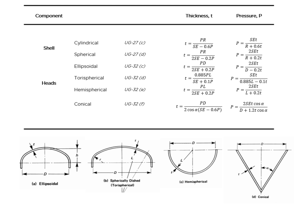
In particular, ASME Section VIII, Division 1 provides formulas for determining thickness and maximum allowable stress of basic components for Pressure Vessels. Equipment design according to this code does not require a detailed assessment of stresses.
The design method uses design pressure, allowable stress and specific formulas according to geometry of the component subject to design. ASME requires that pressure vessels are designed considering the most severe conditions subjected to the vessel, including the normal operation and other conditions such as start-up and shut-down. It’s necessary to have in mind several considerations for the adequate design. One of them is the design pressure, in order to determine it is necessary to know the Maximum Allowable Working Pressure (MAWP) of the component. That is, the maximum pressure permissible at the top of the vessel in its normal operating position at a specific temperature. Other consideration is the Design Temperature: the maximum and minimum design temperatures will determine the maximum (and minimum) allowable stress for the material to be used in the vessel. The minimum design temperature would be MDMT (Minimum Design Metal Temperature). Other important factor is the maximum allowable stress of the material which, as mentioned, depends on the temperature design and these values of stresses include certain safety margins. Also, it’s necessary to take into account an extra thickness in order to avoid the negative effects that may appear due to corrosion. All design considerations for the complete design of a pressure vessel are collected in paragraphs UG-16 to UG-35 of ASME VIII Division 1.
The designer must be familiar with the different failures that may occur and to take them into account in the design stage. These different failure modes are grouped in four categories:
- Material: Can be due to improper material selection and / or material corrosion, among others.
- Design: An incorrect input data or design procedure can lead to design failure
- Fabrication: Due to gross fabrication errors or poor welding qualities
- Service: Change in service condition or unexpected operations
The four previous categories describe “why” the vessel failure may occur. The failure types are: Elastic deformation, excessive plastic deformation, brittle fracture, stress rupture, plastic instability, high strain, stress corrosion and corrosion fatigue. More details about fatigue failure can be found here
In order to avoid equipment failure, the designer must take into account which loads will be involved in the process: steady loads applied continuously such as internal or external pressure, thermal loads and wind loads among others, are sometimes combined with Non-Steady loads, variable and short duration, like earthquakes, erection, transportation or start up – shut down. In particular, part UG-22 of the mentioned code collects all loadings to be considered in the design of a vessel.
On the other hand, several processes involve cyclic loads and thermal stresses, and other approaches more adequate for these cases are needed. Usually, instead of design by rules, design by analysis is used. This approach is collected by ASME in Section VIII Division 2. The combination of both approaches (Design by rules and Design by Analysis) results in a safer, more accurate and economically efficient design.


