One important issue for society nowadays is the control of contaminant emissions to the atmosphere coming from a variety of industrial and public works sites. Be it for environmental or regulatory reasons, or simply for neighbourhood health and comfort, a tight grip on contaminant levels is the way to go in the future.
In SDEA_Engineering Solutions we have used our experience with CFD analyses and worked on a wide range of projects aimed at reducing the industrial damage to the environment and public health; be it particulate dispersion control in large industrial storage piles, contaminant dispersion inside sewage treatment plants, or retro fitment for equipment in power plants in order to use cleaner energy sources with increased efficiency. In this blog post, we will talk about some of our work studying wind surface patterns over storage piles and alternatives to reduce emissions from them.
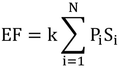
According to the US Environmental Protection Agency [EPA] the emission factor [EF] is dependent on the particle size [k], pile surface area [S] and erosion potential at fastest wind speed [P]. This erosion potential value is itself dependent on the friction velocity.
Friction velocity threshold value [ut*] is the minimum friction velocity [u*] that is required in order to start the movement of a particle from the pile or soil surface, occurring when the drag and lift forces are higher than the gravity and inter-particle cohesive forces. This friction velocity [u*] is dependent on the Wall Shear Stress [Pa] and density. So, after these considerations are taken into account, if u* <= ut*, no emissions to the environment are expected.
In order to accurately calculate these factors, and determine the current situation, the wind data was studied. Here, the wind rose is used, where the frequency of wind per direction is detailed with color bands for the wind speed range (the longer the bar, the more frequent that wind direction is).

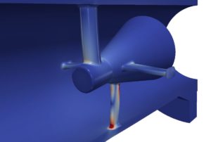
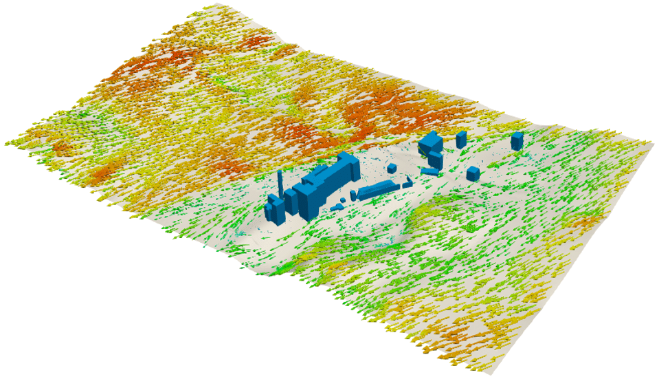
With this information, the most severe winds were targeted for the full CFD study. A detailed high resolution 3D model of the pile surroundings, including buildings, chimneys and other equipment was developed using a point cloud.

The CFD mesh for the 3D model was constructed. In order to capture the details in the most important areas, local finer sizing was used in the vicinity of the buildings and piles. For such a huge computational domain, this becomes necessary as having a finer element size in the far field would imply much higher computational power and calculation time with a limited effect on the relevant variables.

After the CFD calculation for the current geometry, results were interpreted and the preliminary mitigation alternatives were proposed. Several barrier designs were developed in order to lower the friction velocity over the storage piles.
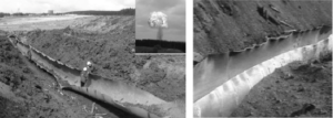
In this image, we can see the friction velocity contours on the storage piles before and after the installation of one of the barrier designs. The contours clearly show how the new design resulted in a lower superficial wind speed, resulting in a much lower probability of particle dispersion.

The CFD calculations have provided a fast study of this problem, with insights into the optimal solution and the ability to test several alternatives in a reduced time frame.