
This article explains the use of advanced FEA analysis for evaluating the structural behaviour of Economizer Heat Exchanger equipment and compares the designs obtained through different design codes.
This example is a heat exchanger with a bellow expansion joint and the reason of performing this study is because of a transition zone between two parts with different thickness, in order to assess the failure risk in that zone. On one hand, the heat exchanger design has been performed according to ASME VIII Div. 1 code using design by rules and shell thickness value obtained is 40 mm. On the other hand, the design of expansion joint has been performed according to Standards of the Expansion Joint Manufacturers Association (EJMA) and the minimum required thickness obtained is 30 mm. Is there a discrepancy? Keep reading if you are interested in finding what is going on.
The SDEA advanced engineering team put their hands on the problem using design by analysis on the bellow design.

Flexible Shell Elements (FSE) are often used in fixed tubesheet heat exchanger in order to reduce shell and tube longitudinal stresses or tube-to-tubesheet joint loads. Ligth gauge bellows type expansion joints within the scope of the EJMA Standard are not included within the purview of this section.
The Tubular Exchanger Manufacturers Association (TEMA) Code, according to RCB-8 part, provided guidelines for determining stresses using a 2-dimensional Axisymmetric Finite Element Model (FEA) for the FSE or FSE combinations.
According to the problem described above, and considering the guidelines provided by TEMA for modelling FSE, the procedure used to obtain the answer to this problem is exposed in the following lines:

Boundary Conditions for FSE analysis RCB-8.42
At first, the CAD model (2D Axisymmetric geometry of FSE) is meshed considering eight node quadratic axisymmetric elements and the boundary conditions shown in figure RCB-8.42. The axial translation of the FSE is restringed at the FSE axial plane, pressure of shell side is applied in the inner face of FSE and an axial displacement is applied for stress determination.
In order to evaluate the stress, it’s necessary to establish the minimum number of stress classification lines (SCL) and to compute linearized both membrane and membrane+bending stress intensities at each SCL in order to compare these stress values with the allowable stress limits defined in the design Code.
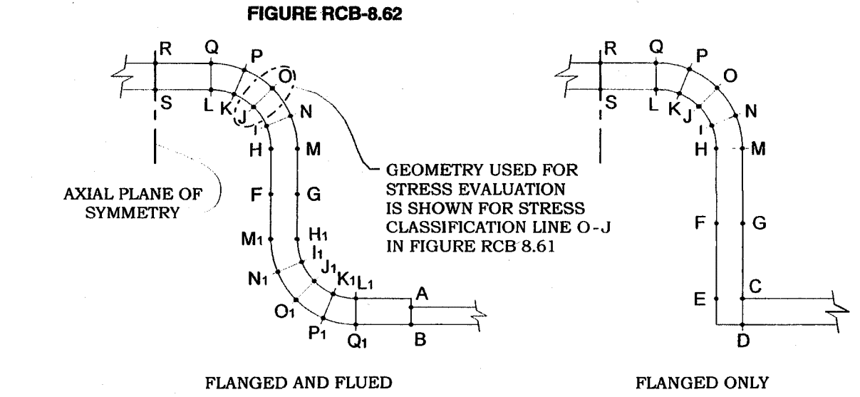
Stress Classification Lines for Evaluating Stresses RCB-8.62
The methodology for evaluating stresses is not specified in part RCB-8, so the code chosen for this purpose is ASME VIII Divisions 1 and 2.
In the context of bellows expansion joints design, Division 1 provides the allowable stress in bellows, according to part 6 of Mandatory Appendix 26 (Design of U-shaped unreinforced bellows):
- S1 ≤ S
- S2 ≤ S
- S3 + S4 ≤ KMS
where S1 is the circumferential membrane stress in bellows tangent; S2, circumferential membrane stress in bellows; S3 and S4 are meridional membrane and bending stresses, respectively, all of them obtained due to pressure. S is the allowable stress of bellows material at design temperature. Stresses in bellows due to deflection are only considered in fatigue analysis.

Stress in Bellows
Km is equal to 1.5·Ysm for as-formed bellows and 1.5 for annealed bellows, where Ysm is the yield strength multiplier which depends on the material. The value of Km varies between 1.5 and 3.0. Similarly, EJMA Standard collects the same stresses criteria in 4.13.1 (Design Equations for Unreinforced Bellows).
It is important to remark the fact that the combination of membrane plus bending stress on the convolution peak is compared against the allowable stress, scaled by a factor of 3 in this case. This is paramount and takes into account the hardening effect from the forming manufacture method, where the material goes well beyond yielding, resulting in hardening after the process.

Design Equations for Unreinforced Bellows [EJMA Standard]
On the other hand, according to Table 5.6 of ASME Section VIII Division 2, the next stresses classification should be used, depending on the location and the origin of the stresses:
- Pm < S
- PL < S
- PL + PB < 1.5S
where Pm is the maximum primary membrane stress; PL, local membrane stress and PB, primary bending stress.
So, in order to analyse the stresses in the different Stress Classification Lines of FSE, stresses classification provided by Division 2 and allowables stresses in bellows provided by Division 1 (and EJMA) are considered.

Stress Classification Lines for Stress Evaluation

Von Mises Stress Contours of FSE
2D-Axisymmetric FEA is performed for the FSE applying the boundary contidions described above and the stress values are evaluated in one of each SCL chosen for this model. According to the criteria exposed previously, table with SCL values is presented and the stress values obtained are below of the allowable ones:

Stress Classification Lines Results
This work was addressed in order to give an answer to the question if there is some discrepancy between design codes used for the design of the heat exchanger (ASME VII Div 1 Code used for calculating the minimum required thickness of the shell and EJMA Code used for mechanical design of bellow expansion joint) and to predict the structural behaviour in the transition zone between both. In this scope, a FEA method was used in order to analyse this problem. In view of the FEA analysis results , it can be reasuring to see the good behaviour of the system and the transition zone between the parts with different thickness: it is safe under the design conditions for different pressure and temperature parameters considered. It’s a good practice to combine Design by Rules with Design by Analysis, using FEA methods in order to validate the design by rules performed beforehand.


